Understanding Fluid Power

by kind permission of Erik Lanke, President of NFPA.

What is Power Transmission?

Standard electric motors typically rotate at 1,000 or 3,000 revolutions per minute (synchronous no-load speed – rpm) – much faster than is practical for most machines. Internal combustion engines also rotate at thousands of rpm when powering equipment. Some form of power transmission, therefore, is needed to convert power from the motor or engine to a more useable form – slower speed and often, linear motion instead of rotary.

Mechanical power transmission methods include gear, chain, belt and other mechanical drives that convert the high-speed mechanical power from the engine or motor’s output shaft to a slower speed with higher torque (twisting force). Mechanical power transmission components also include ball screws, rack and pinion assemblies, chain drives, and other components that convert rotational motion and torque to linear motion and force.

Electrical methods of power transmission regulate electrical power to the motor to control speed and torque. These methods cannot convert the rotary motion of a motor to linear. When linear output is needed a linear motor may be used, but its high cost generally makes a mechanical rotary-to-linear motion device more practical for producing linear motion and force.

In many cases, however, mechanical and electrical methods cannot provide a practical power transmission solution. In these cases, fluid power – whether hydraulic or pneumatics – is used because it can deliver linear and rotary motion with high force and torque within a smaller, lighter package than is possible with other forms of power transmission

A cement mixer, for example, illustrates how different methods of power transmission may be used. Early cement mixers used mechanical drives driven by the truck’s engine or transmission. A system of gears, chain drives and drive shafts provided the speed and torque necessary to rotate the heavy drum of concrete, but speed was difficult to control. The rotational speed of the drum depends upon the engine or transmission speed. As the driver changes gear, the drum would speed up or slow down and rarely rotated at the desired speed. In addition, the complexity and bulk of all the mechanical components were highly maintenance intensive.

An electrical drive could provide good speed control but would require a high-power electric generator, controls and a motor to drive the drum. The motor would be prohibitively large or would require a large gearbox to achieve the low rotational speed of the mixer drum. Either solution would result in a much larger and heavier installation than a hydraulic drive.

Hydraulic drives are the primary choice for cement mixer drives. They use a pump, hydraulic motor and valves to control speed regardless of the engine or transmission speed. The drum rotates at optimum speed, or maybe controlled manually. The components are relatively compact with the pump tucked away within the framework of the truck and the hydraulic motor is only a small fraction of the size of a comparable electric motor gearbox combination.

What is Fluid power?

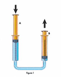
Fluid power is a term describing hydraulics and pneumatics technologies. Both technologies use a fluid (liquid or gas) to transmit power from one location to another.

With hydraulics the fluid is a liquid (usually oil but can be water) whereas pneumatics uses a gas (usually compressed air). Both are forms of power transmission, which is the technology of converting power to a more useable form and distributing it to where it is required. The common methods of power transmission are electrical, mechanical and fluid power, although they are sometimes viewed as competing technologies, no single method of power transmission is the best choice for all applications. In fact, most applications are served by a combination of technologies. Fluid power, however, offers important advantages over the other technologies.

Fluid power systems easily produce linear motion using hydraulic or pneumatic cylinders, whereas electrical and mechanical methods usually must use a mechanical device to convert rotational motion to linear. Fluid power systems generally can transmit equivalent power within a much smaller space than mechanical or electrical drives, especially when extremely high force or torque is required. Fluid power systems also offer simple and effective control of direction, speed, force and torque using simple control valves and can be integrated with sophisticated electronics for more precise control. Fluid power systems often do not require electrical power, which eliminates the risk of electrical shock, sparks, fire and explosions.

Fluid Power Advantages

Hydraulic and pneumatic systems share many benefits for the machines in which installed. These include:

>High power to weight ratio: you could probably hold a 3kW hydraulic motor in the palm of your hand but a 3kW electric motor might weigh 20kg or more

>Safety in hazardous environments: they are inherently spark-free and can tolerate high temperatures

>Force or torque can be held constant: this is unique to fluid power transmission

>Hydraulic and pneumatic motors can produce high torque whilst operating at low rotational speeds. Some fluid power motors can even maintain torque at zero speed without overheating

>Pressurised fluids can be transmitted over long distances and through complex machine configurations with only a small loss in power

>Multi-functional control: a single hydraulic pump or air compressor can provide power to many cylinders, motors or other actuators

>Elimination of complicated mechanical trains of gears, chains, belts, cams and linkages

>Motion can be almost instantly reversed

Hydraulic and pneumatic systems are widely used both in stationary (industrial) and mobile equipment. Hydraulics also used when heavy force or torque is involved, such as lifting loads weighing several tonnes, crushing or pressing strong materials like rock and solid metal, digging, lifting and moving large amounts of earth.

Although pneumatics is capable of transmitting high force and torque, it is more widely known for fast-moving, repetitive applications such as pick-and-place operations, gripping and repetitive gripping or stamping. In both cases, electronic controls and sensors have been implemented into fluid power systems for the last few decades. These electronics make hydraulic and pneumatic systems faster, more precise and efficient, and allow them to be tied into statistical process control and other factory and mobile equipment control networks.

Fluid Power Components

Fluid power systems consist of multiple components that work together or in sequence to perform some action or work. People well versed in fluid power circuit and system design may purchase individual components and assemble them into a fluid power system themselves. Many fluid power systems, however, are designed by manufacturers, consultants and other fluid power professionals who may provide the system in whole or in part. The major components of any fluid power system include:

> A pumping device: a hydraulic pump or air compressor to provide fluid power to the system

> Fluid conductors: tubing, hoses, fittings, manifolds and other components that distribute pressurised fluid throughout the system

> Valves: devices that control fluid flow, pressure, starting, stopping and direction

> Actuators: cylinders, motors, rotary actuators, grippers, vacuum cups and other components that perform the end function of the fluid power system

> Support components: accumulators, filters, heat exchangers, manifolds, hydraulic reservoirs, pneumatic mufflers and other components that enable the fluid power system to operate more effectively

Electronic sensors and switches are incorporated into many of today’s fluid power systems to provide a means for electronic controls to monitor operation of components. Diagnostic instruments are used for measuring pressure, temperature and flow in assessing the condition of the system, also, any trouble shooting.

What is Hydraulics?

To visualise a basic hydraulic system, think of two identical syringes connected together with tubing and filled with liquid (see Figure 1).


Syringe A represents a pump and Syringe B represents an actuator, in this case a cylinder. Pushing the plunger of Syringe A pressurises the liquid inside. This fluid pressure acts equally in all directions (Pascal’s Law) and causes the liquid to flow out the bottom, into the tube and into Syringe B. If you placed a 5kg object on top of the plunger of Syringe B you would need to push on Syringe A’s plunger with at least 49.05 Newtons of force to move (mass 5kg x acceleration due to gravity 9.81m/s) to move the weight upward. If the object weighs 10kg you would have to push with at least 98.1N of force to move the weight upward.
If the area of the plunger (which is a piston) of Syringe A is 1 square centimetre and you push with 50N of force, the fluid pressure will be 50N/cm² (or 0.5 Megapascal or MPa). As fluid pressure acts equally in all directions, if the object on Syringe B (which, again has an area of 1 square centimetre) weighs 10kg, fluid pressure would have to exceed 0.981MPa (or 9.81 bar) before the object would move upward.

If we double the diameter of Syringe B (see Figure 2) the area of the plunger becomes four times what it was. This means a 10kg weight would be supported on 4 square centimetres of fluid. Fluid pressure would only have to exceed 24.53N/cm² (10kg x 9.81m/s²) to move the 10kg object upward. So, moving the 10kg object would only require 24.53N of force on the plunger of Syringe A, but the plunger on Syringe B would only move upward a quarter as far as when both plungers were the same size. This is the essence of fluid power. Varying the sizes of pistons (plunges) and cylinders (syringes) allows multiplying the applied force.

In actual hydraulic systems, pumps contain many pistons or other types of pumping chambers that are driven by a prime mover (usually an electric motor, diesel engine or gas engine) that rotates at several hundred revolutions per minute (rpm). Every rotation causes all of the pump’s pistons to extend and retract – drawing fluid in and pushing it out to the hydraulic circuit in the process.

Hydraulic systems typically operate at fluid pressures of tens of MPa (1 MPa = 10 bar). So a system that can develop 200 bar (20 MPa) can push with 100,000N of force from a cylinder about the same size as a can of drink.

Hydraulic Applications

Mobile equipment is probably the most common application of hydraulics. Whether its construction, mining, agriculture, waste reduction or utility equipment, hydraulics provides the power and control to tackle the task, and often to provide motive power to move equipment from place to place and over difficult terrain – especially when track drives are involved. Hydraulics is also widely used in heavy industrial equipment in factories, in marine and offshore equipment for lifting, bending, pressing, cutting, forming and moving heavy work pieces. Other industries where hydraulics is advantageous:

> Agriculture
> Construction
> Entertainment
> Oil and gas, and marine
> Waste and recycling
> Energy
> Machine tools
> Metal forming
> Military and aerospace
> Mining
> Utility equipment

What is Pneumatics?

The principles of pneumatics are the same as those for hydraulics, but pneumatics transmits power using a gas instead of a liquid. Compressed air is usually used but nitrogen, or other inert gases, can be used for special applications. With pneumatics air is usually pumped into a receiver using a compressor. The receiver holds a large volume of compressed air to be used by the pneumatic system as needed. Atmospheric air contains airborne dirt, water vapour and other contaminants, so filters and air dryers are often used in pneumatic systems to keep compressed air clean and dry, which improves reliability and service life of the components and system. Pneumatic systems also use a variety of valves for controlling direction, pressure and speed of actuators.

Most pneumatic systems operate at pressures of about 10 bar or less. Due to the lower pressure, cylinders and actuators must be sized larger than their hydraulic counterparts to apply an equivalent force. For example, a hydraulic cylinder with a 25 cm diameter piston (19.34 square centimetres) and fluid pressure of 50 bar (5 MPa) can push with 9,815N of force. A pneumatic cylinder using
10 bar air pressure would need a bore of almost 11.2 cm (98.15 square centimetres) to develop the same force.

Even though pneumatic systems usually operate at much lower pressures than hydraulic systems, pneumatics holds advantages that makes it more suitable in certain applications. As pneumatic pressures are lower, components can be made of thinner and lighter weight materials such as aluminium and engineered plastics, whereas hydraulic components are generally made of steel and ductile or cast iron. Hydraulic systems are often considered rigid whereas pneumatic systems usually offer some cushioning or ‘give’. Pneumatic systems are generally simpler because air can be exhausted to the atmosphere whereas hydraulic fluid usually is routed back to a fluid reservoir.

Pneumatics also holds advantages over electro-mechanical power transmission methods. Electric motors are often limited by heat generation. Heat generation is usually not a concern with pneumatic motors because the stream of compressed air running through them carries heat from them. Furthermore, pneumatic components require no electricity, nor do they need the bulky, heavy and expensive explosion-proof enclosures required by electric motors. In fact, even without special enclosures electric motors are substantially larger and heavier than pneumatic motors of equivalent power rating. In addition, if over-loaded, pneumatic motors will simply stall and not use any power. On the other hand, electric motors can overheat and burn out if over-loaded. Moreover, torque, force and speed control with pneumatics often requires simple pressure or flow-control valves as opposed to more expensive and complex electrical drive controls. As with hydraulics, pneumatic actuators can instantly reverse direction whereas electro-mechanical components often rotate with high momentum that can delay changes in direction.

Another advantage of pneumatics is that it allows using vacuum for picking up and moving objects. Vacuum may be thought of as a negative pressure – by removing air (evacuating) from the volume between two parts, atmospheric pressure outside the volume pushes the parts together. For example, attempting to pick up a single sheet of paper or a raw egg presents a challenge with conventional grippers, but with a vacuum pneumatic system, evacuating a suction cup in contact with a sheet of paper or eggshell will cause atmospheric pressure to push the paper or egg against the cup, allowing it to be lifted.

Pneumatic Applications

Factory automation is the largest sector for pneumatics technology that is widely used for manipulating products in manufacturing, processing and packaging operations. Pneumatics is also widely used in medical and food processing equipment. Pneumatics is typically thought of as pick-and-place technology where pneumatic components work in [unison] to perform the same repetitive operation thousands of times per day. Compressed air can have a cushioning effect so is often called on to provide a gentler touch than that of hydraulics or electro-mechanical drives can usually provide. In many applications pneumatics is used more for its ability to provide controlled pressing or squeezing as it is for fast and repetitive motion. Moreover, electronic controls can give pneumatics systems positioning accuracy comparable to that of hydraulic and electro-mechanical technologies.

Pneumatics is also widely used in chemical plants and refineries to actuate large valves. It is used on mobile equipment for transmitting power where hydraulics or electro-mechanical drives are less practical or not as convenient and in mobile trucking for various vehicle functions. Of course vacuum is used for lifting and moving work pieces and products. In fact, combining multiple vacuum cups into a single assembly allows lifting large and heavy objects. Industries where pneumatics is advantageous:

>Food and beverage
>Factory automation
>Material handling
>Medical
>Off and on-highway vehicle systems
>Packaging