
Closed-Loop Motion Control Simplifies Non-Destructive Testing
27 Nov 2020
By Tim Gessner of Delta Motion Limited
Repetitive non-destructive testing (NDT) applications abound, and designers should consider using programmable motion controllers to power flexible testing scenarios. Consider fluid power where a predictable amount of force must be exerted, where the compressibility of the fluid medium can be used to avoid damage to the device under test, or where heavy loads must be held or moved as part of the testing process. Electric servos can also be used to power test axes if force can be controlled.
Simulated reality in shorter timespans
Motion actuators can be driven to simulate real-world conditions, such as applying force to aircraft landing gear to simulate the loads encountered in an actual runway landing situation. Similarly, the hydraulic actuator in a building truss tester can apply loads to simulate harsh environmental conditions such as wind and snow loading. In these applications—and others such as a vehicle leaf-spring tester and a medical prostheses tester—motion actuators can apply the same usage patterns over a period of days or weeks that the items under test would normally encounter over a lifetime.
Closed-loop control of position and force makes non-destructive testing possible
Gaining the full potential from motion sources in testing applications requires an electronic motion controller implementing closed-loop control of the pressure or force being applied to the device under test. Precise position and/or speed control are also necessary. Simply controlling the position of an actuator is not adequate because it cannot detect subtle changes in the physical properties of the subject device unless the force required to move or flex the device can be monitored closely. In a fluid power system, the force being applied by an actuator can be obtained by monitoring the difference between pressures on either side of the piston. In a mechanical motion system, force can be measured with a load cell.
Making all the right connections
A hydraulic leaf-spring tester is designed to flex the spring repetitively while measuring the force required to displace the spring leaves (see the Figure 1 diagram). The motion controller connects to pressure sensors for measuring force and to a magnetostrictive linear displacement transducer (MLDT) for determining the position of the actuator. In a typical test operation, such as that shown in Figure 1, position control may be used to put the actuator in approximately the proper position for applying a controlled amount of force. An electronic motion controller can smoothly transition between controlling position to controlling pressure/force.
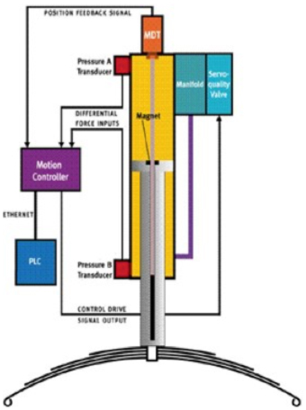
Figure 1. Hydraulic leaf-spring tester controls both the position and force being exerted by the actuator.
The motion controller drives the hydraulic cylinder by sending analog signals to a proportional servo valve that can make precise adjustments (sinusoidal or other waveforms) to cylinder pressure to control the hydraulic actuator’s force or positioning. A hydraulic fluid accumulator (not shown in Figure 1) stores hydraulic pressure, ensuring that consistent hydraulic-system supply pressure is available to operate the servo valve during spring compression cycles.
Programming the motion
As mentioned, NDT programs often involve the application of repetitive stress cycles on the device being tested. A motion controller that supports direct execution of repetitive motion operations simplifies the set-up of testing profiles. For example, some motion controllers can produce precisely repetitive motion sequences such as trapezoidal profiles, ramp up/down profiles, and sine waves (see Figures 2a and 2b).
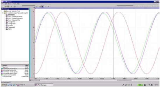
Figure 2a. A plot of continuous sinusoidal motion produced by a motion controller. The red curve plots axis position versus time, and the violet curve plots velocity versus time. As this system is tuned precisely, the actual and target position and velocity curves overlap.
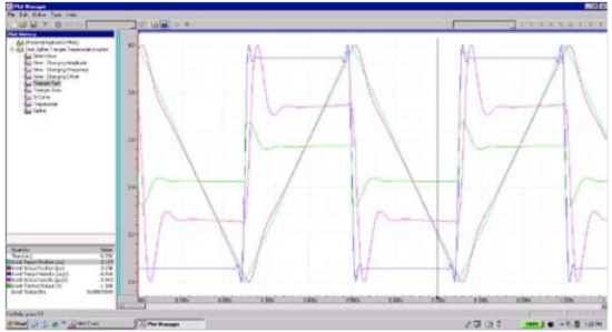
Figure 2b. A plot of continuous ramping up and down motion produced by a motion controller. This system is not as precisely tuned as the one in Figure 2a because the target and actual position and velocity curves do not precisely match.
Some motion controllers can also generate complex, repetitive profiles using spline functions.
Interfaces to industry standard test environments
Another factor that contributes to building a good platform for non-destructive testing applications is the ability to interface with popular data acquisition and control software programs that are hosted on PCs, such as National Instruments’ Labview or Microsoft Visual Basic or Visual C++. We recommend a software component that enables direct access from Windows-based PCs running data acquisition software to the motion controller. These software components enable the PC application to read and write registers in the motion controller and issue commands. Direct connection occurs via serial port or Ethernet access.
Application Example: Electronic control delivers new capabilities for a leaf-spring tester
When taking a systems approach to developing a test system, new capabilities can be enabled, such as the ability for outside control modules to interrogate the system and analyze process data. For example, leaf-spring manufacturer Rockwell American of Seagoville, Texas, used data on the force being applied to springs under test to identify how structural parameters in the steel change over time.
In Rockwell American’s leaf-spring tester (Figure 1), the controller accurately follows an operator selectable, internally-generated target-force profile using an HMI. Each spring movement is controlled by continually adjusting drive output to the hydraulic valve 1000 times per second. Simultaneously, the minimum and maximum spring deflections are being monitored in real time during the force cycling and compared against allowable limits to determine any change in the spring’s properties. For each spring tested, these limits are found when the motion controller is commanded to enter force control (initiated by the operator via the HMI’s touch screen). At the beginning of the testing cycle, the system compresses the spring to minimum and maximum force set points while recording and storing the corresponding minimum and maximum spring deflections. This capability was very useful in helping Rockwell American diagnose and document a recent raw material quality problem. Another significant savings occurred in set-up time when shifting between spring types.
If the position of the hydraulic actuator were to exceed operator-specified tolerances during the continuous force control-cycle testing, the spring properties may be changing, the spring may soon break, or one leaf in the spring may have already broken. If this condition happens, the motion controller’s continuous monitoring of position tolerances during force cycling will lead to an automatic system shut down. With these controls, the machine can run continuously with a minimum of supervision. The machine can also capture and plot test data for post-test diagnostics and recordkeeping.
Application Example: Prosthetics tester leverages repetitive motion profiles and force/position control
The International Standards Organization (ISO) requires prosthetics manufacturers to test elastic ankle joints to ensure they can flex under realistic conditions through at least two million cycles. Key to ensuring realistic testing is making sure that the displacement of the joint is within a certain limit during each cycle when a particular force is applied.
The tester uses two pneumatic cylinders, controlled by a two-axis motion controller. One cylinder is positioned to press on the heel and the other pushes on the toe of an artificial foot (see Figure 4). A load cell affixed to each cylinder measures the force being applied, while a MLDT affixed to each piston measures the position of each actuator. As the test system cycles, the cylinders alternate their motion to flex the joint. During each cycle, the motion controller increases the force being applied on each cylinder until it reaches a predetermined set point, and then it measures the amount of deflection of the joint to ensure that it is less than the maximum allowable.
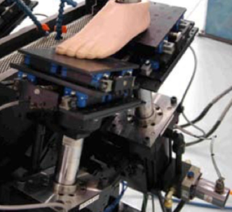
Figure 4. A pneumatic prosthetic foot tester showing one cylinder pressing on the toe and one on the heel of an artificial foot.
Because data on the deflection amount is collected every cycle (by a programmable logic controller that reads registers in the motion controller), the tester can measure the onset of fatigue before a catastrophic failure occurs. Good motion controllers can cycle the tester between two and three times per second to double the throughput of the testing facility.
To keep the weight of the test system as low as possible, pneumatics was chosen for this tester (rather than hydraulics). However, since air is more compressible than oil, system tuning became a challenge. Real-time motion plotting and tuning tools simplified the system tuning for optimal performance.
Application Example: Race car suspension tester makes eight axes move simultaneously to simulate real road-racing conditions
This example uses an eight-axis motion controller in an advanced diagnostic testing system that provides racing teams with detailed data about the chassis and suspension of their cars in several simulation scenarios. The system (Figure 5) provides precise suspension motion while measuring bump steer, camber change, and wheel loading; it allows suspension component interference checking throughout the suspension travel range. Data gathered enables the suspension of a vehicle to be completely characterized and tuned for optimal performance while on the simulator.
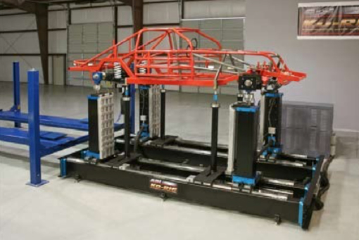
Figure 5. Vehicle suspension test system.
The motion controller can be programmed to control both force and position simultaneously on all eight motion axes, and it can synchronize or “gear” the motion of slave axes to the motion of master axes. This enables performance of the system to be scaled while maintaining the relationships between the axes without requiring reprogramming of the motion. A software toolset supports graphing of motion profiles and automated tuning tools to speed the optimization of test profiles.
Conclusion
Electronic motion controllers excel at moving multiple hydraulic or pneumatic axes and controlling force and position to generate real-world testing scenarios. Designers should look for motion controllers that provide precise closed-loop control and are supported with instruction sets, development tools, and inter- faces that simplify the programming and tuning of testing profiles.
About the Author
Tim Gessner, European Director of Business Development at Delta Computer Systems, is responsible for sales and distribution management throughout Europe. Prior to this role, he worked for 17 years in engineering development and applications support for Delta, playing key roles in the development of RMC motion controllers. Gessner holds two Bachelor of Science degrees, two Master’s degrees, and a PhD from the University of Edinburgh in Scotland.
Delta Computer Systems, Inc.
For almost 40 years, Delta Computer Systems, Inc. has supplied motion controllers and other industrial products that enable better performing machines. Delta’s RMC Motion Controllers are used for hydraulic, pneumatic, and electric closed-loop control in a wide array of single- and multi-axis control and testing applications. For more information contact Delta at (360)254-8688, email technicalsales@deltamotion.com, or visit us at www.deltamotion.com.”