
Selecting Motion Controllers for Metals Industry Applications
23 Oct 2020
By Tim Gessner, Delta Motion
The metals manufacturing industry is constantly evolving to improve machine productivity and produce smaller product batches. Machine designers and integrators have several concerns: decreasing the impact of machine changeover times, the variability of operator skills, and accuracy of the quality and throughput of manufacturing processes. How they address these concerns can have a major impact on decreasing lifecycle costs.
While hydraulics provide the power for even the heaviest-duty applications, traditional hydraulic control systems often lack the precision to produce highly accurate and repeatable motion. For new machines and upgrades of older machines, one way to meet cost and productivity goals is to use a modular system design that incorporates a digital motion controller.
Modular systems simplify design
Modular design of control systems is not a new concept, but constructing modular systems using components from different vendors has been difficult. In the past, control elements from one vendor didn’t communicate easily with elements from another vendor. Thus, machine designers needed to invest extra time and money to get different controllers to work together through specialized I/O. Designers often used single-vendor solutions, which were sometimes sub-optimal for the control task. The advent of standard industry buses has changed this. Designers can now use control-system elements from different vendors with standardized interfaces to a “fieldbus” that forms the backbone of the control system architecture (see Figure 1).
Ethernet is one of many fieldbuses designers can choose. Other buses, such as PROFIBUS, provide different features and advantages.
 Figure 1. Modular control system based on Ethernet.
Key control-system components in a typical system include the programmable logic controller (PLC), which typically acts like a functional supervisor for the machine; it issues motion commands and communicates with the human-machine interface (HMI). The machine operator uses the HMI to set up the machine’s operation and view diagnostic messages.
Selecting a motion controller for metals applications
In a motion controller, high performance is often expressed in terms of support for high scan rates, as well as the rates at which the controller tests its inputs, makes decisions, and generates controlling outputs. An advanced motion controller can close the control loop one thousand times per second or more. This is up to eight times the rate of some control systems used in older machines. Faster scans and closed-loop motion control mean faster machine operation and higher productivity for the machine owner.
Motion control performance is also enhanced through the proper selection of the system’s transducers, the devices that directly measure the parameters being controlled (e.g., position and pressure). For applications requiring precision and robustness, the favored position transducers are magnetostrictive linear displacement transducers (MDTs). For optimal performance, designers should look for motion controllers that provide a direct interface to popular MDT devices as well as analog, Synchronous Serial Interface (SSI), and quadrature feedback devices.
Smooth motion improves quality, extends machine life
For machines used in metal fabrication, high-quality output stems from smoothly controlled operations. Control system designers need a motion controller that can transition from hydraulic control based on position inputs to hydraulic control based on pressure (or force), without stopping the motion. Smooth motion also requires smooth valve control, and the motion controller should provide control signals to drive a proportional valve, adding or subtracting hydraulic pressure in minute amounts. During a system’s smooth operation, hydraulic pressure transients and pressure overshoot are reduced, decreasing the potential for hydraulic leaks and extending the life of the machine. Some older-generation hydraulic control systems control via cylinder-position sensing only, and they use valving with only “open” and “closed” positions. This can result in imprecise controls and lower quality output, as well as increase the frequency of system maintenance.
Multi-axis and “hybrid” control capabilities
Some complex metal-forming applications involve multiple motion axes. For these systems, designers should look for motion controllers with multi-axis control capabilities. Beyond simply driving multiple actuators, good motion controllers should be able to “gear” one axis’s speed of motion with that of another so that the performance of the machine to be scaled can meet varying production demands and varying material types. This flexibility is very difficult (or impossible) to achieve with human or limit-switch-based controls.
Also, because many metal-forming machines are “hybrid” systems that have a mixture of hydraulic and electromechanical motion sources, designers should look for multi-axis controllers that can coordinate the use of both types of motion to gain the best benefits of both.
Advanced controllers reduce system hardware costs by controlling each hydraulic cylinder or motor with a single valve, even in position/pressure applications, as opposed to many older hydraulic motion-control systems that require two valves.
Tuning for optimal performance and throughput
Machine designers must be able to optimize motion controls. In typical machine operation, the controlling PLC programs the motion controller by writing sequences of motion commands called “steps” into the controller.
Designers should look for motion controllers that have supporting development tools to make the most of the controller/HMI connection. Designers can use these tools to monitor how closely the actual motion profile matches the target and make adjustments to control loop parameter values to reduce positioning errors.
A recent trend in the motion industry is the availability of automated tuning tools that simplify and shorten the design optimization process. For example, the Tuning Wizard (see Figure 2) builds a set of mathematical system models and determines which model best fits the real system. The Tuning Wizard next prompts the user to set the desired system response between “conservative and aggressive” using a computer mouse and slider bar; it then computes the optimum PID and feed-forward gains.
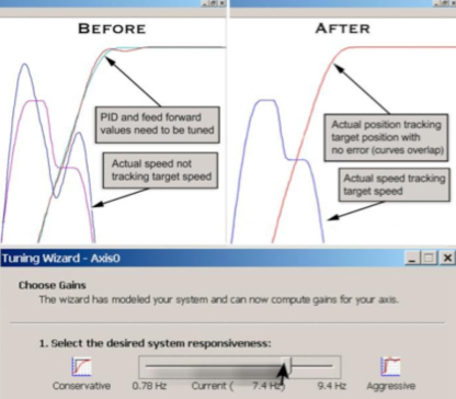 Figure 2. Delta Computer Systems’ Tuning wizard adjusts motion plots to reduce motion errors.
Case Study 1: Metal Forming
Large satellite antenna dishes are manufactured to very tight tolerances in three dimensions. Dishes that range from 6 to 16 feet in diameter are produced by press-forming large, flat aluminum blanks to hemispherical forms (“chucks”) made of hardened steel. As the chuck and circular aluminum blank are rotated, a ball-shaped press foot (spin ball) comes into contact with the blank. As the blank and chuck rotate, the spin ball forms the blank to the shape of the chuck by moving from the center to the outer edge of the blank along the curved contour of the chuck (see Figure 3). After the dish is formed to the chuck, a form shoe and a forming roller generate the lip on the outside circumference.
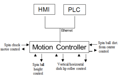 Figure 3. Metal Forming control system block diagram
To ensure precise tolerances, a five-axis motion system is required, with some axes moving linearly while others rotate. Hydraulic power operates the spin ball and lip-forming tool, while electric motors power the rotational axes and those linear axes not involving pressure.
The system design engineers used electronic motion controllers to ensure repeatable operation at high tolerances and to support quick and easy control reconfiguring to manufacture different-sized dishes. The controllers provide flexibility in handling a diverse set of motion control tasks, including the ability to handle closed-loop position and pressure control of hydraulic actuators. They connect directly to Ethernet and can run up to 255 motion-event steps independent of the PLC.
The most significant benefits the new control system provides include the ability to change recipes very quickly and easily, which translates to increased manufacturing efficiency. Once the correct manufacturing parameters are established, the dish manufacturing process is precisely repeatable, meeting the tight reflective tolerances of the high-quality product demanded by the manufacturer’s customers, while enabling operation by a diverse range of human operators, domestically and abroad.
Case study 2: Hydroforming
Hydroforming is a manufacturing process in which a metal tube is formed by filling the inside of the tube with high-pressure water and inflating the tube to fill a specially shaped mold. Hydroforming is used where the cross section of the manufactured part changes throughout the part, such as automotive suspension components and plumbing fixtures. Although hydroformed parts appear to be cast, they can be made without the finishing costs and processing complexity.
Precision hydroforming has only been possible with the advent of the new generation of hydraulic motion controllers.
Figure 4 shows the main elements in a new hydroforming control system where a motion controller is at the core of the application. The controller controls the hydraulic rams through proportional servo-quality valves, using position feedback obtained from MDTs mounted along the hydraulic piston axes. The controller also has digital I/O interfaces, which it uses to communicate with a PLC and activate a valve that controls the water pressure in the tube.
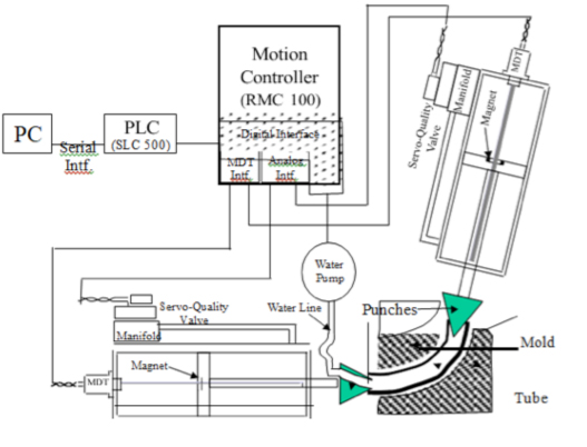 Figure 4. Hydroforming Control System
The motion controller executes a programmed sequence of hydraulic commands to extend the punch rams to their desired positions. Next, it issues a digital command for the water to fill the tube. When the inflation phase is complete, the controller turns off the water and retracts the punches. Finally, the motion controller sends a digital message back to the PLC instructing it to depressurize the mold-holding clamp and open the mold.
The motion steps are programmed into the controller using a PC. The sequence of motion steps are optimally tuned for the manufacture of a particular faucet part, and then the sequence file is stored in the PC for retrieval by the manufacturing engineer as they set up the machine to manufacture that faucet part.
Development software allows users to set control parameters and program the motion sequence by loading values into a step table in the controller.
The software allows measurements to be entered in inches rather than encoded numbers so that users can easily change a few parameters and optimize the system’s operation. To aid the tuning process, the software supports the graphing of actual motion profiles versus target profiles.
Case Study 3: Tube Processing
As with the other case studies, manufacturers of machines that process high-quality tubing for use in automotive exhaust systems, furniture components, electrical conduit, and handles for child-safety seats also have critical motion control requirements.
Tube and pipe manufacturing is about maximizing the number of feet per minute. Older tube mills run at 200 feet per minute, while others may run at 500 or even 1000 feet per minute. The cutters that cut tube segments to length need to cut very quickly, and the effects of the cutting (burrs and dimples at the tube ends), need to be repaired just as quickly to keep up with the cutters. Manufacturers can gain machine cost and productivity benefits by integrating additional functions, such as the removal of internal and external welding imperfections along the length of the tubing.
The sequential process supported by one new tube-processing machine is shown in Figure 5.
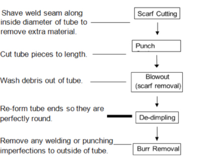 Figure 5. Tube processes
Because many control tasks must be performed simultaneously, the engineers employed functional partitioning in the design: Different controllers specially suited for the tasks they perform also handle different machine functions. The system uses a PLC for master control and operator-interface functions, and a motion controller to control the operation of the eight hydraulic axes. The motion controller uses four axes to control the de-dimpling/de-burring process and four axes to control the inside diameter (ID) scarf removal system (blowout).
To coordinate and control the many complex motion steps in the machine (most of the moving parts, including the rotary motors, are hydraulic), the machine designers chose a motion controller.
To keep all the motors synchronized, the motion controller must be capable of “electronic gearing” in which one system element’s rate of motion is regulated by motion elsewhere in a system.
For example, the motion of the de-dimpling punches is keyed to the motion of the chain that carries the tube past the de-dimpling station. If the chain slows down, the de-dimpler operation also slows down. The operation is keyed off the chain indexing and doesn’t require intervention of an external controller such as a PLC. Because they are tied to other motions instead of discrete events or control inputs, spline functions support smooth acceleration and deceleration.
Using an electro-hydraulic motion controller allowed the machine manufacturer to bring the benefits of hydraulics and electronic control to an application that would have previously required complex mechanical cams and line shafts. By eliminating mechanical workings, the company reduced mechanical wear while using less-expensive system components (hydraulic motors versus electric motors).
Further, to move each end of the tubes down the processing line on separate independently-driven chains, the design uses the motional controller’s rotary synchronization capability. The main sprocket of each chain is driven by its own hydraulic motor (see Figure 6). Two motors drive the chain sprockets to avoid flexing and to allow for variable-length pipe. For proper operation, the motors must be synchronized; and for precise, smooth control, each motor is controlled by a variable hydraulic valve.
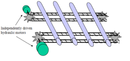 Figure 6. Rotary synchronization of motion controller
The selected controller is unique in its ability to simultaneously control up to eight hydraulic motion axes while smoothly transitioning from position to pressure-based control. Programming motion steps is as easy as entering sequences of coded instructions into a control spreadsheet. This particular controller also supports spline functions that enable “electronic gearing.”
Case Study 4: Die Casting Press
Using advanced motion controllers that connect to a wide range of industry-leading components, machine builders can now select best-of-class system components from multiple vendors. A case in point is a new vertical die-casting machine that produces high-integrity aluminum castings.
Several factors led to the choice of PROFIBUS as the fieldbus communications backbone for the system:
- Compatible parts availability worldwide
- High bandwidth
- Deterministic communications
- Flexible system interfaces to a wide array of system components as specified by machine end customers
With a PROFIBUS interface between the system PLC, motion controller, and peripheral devices, machine operators can set process set-points from their HMI and gather data in a PC-based data acquisition system. The machine designers prefer PROFIBUS because of its support for high, 12Mbits-per-second throughput, which supports real-time data acquisition from a wide array of system devices.
In one customer installation, PROFIBUS provides a connection to a Fanuc six-axis robot that sprays release agent on the die, shot sleeve, and piston (see Figure 7). PROFIBUS also interfaces to a hot-oil system built in Austria (for heating the die) that sends temperature set-points and diagnostics information to the system controller. The machine also provides a PROFIBUS connection to a Fonderex vacuum unit used to evacuate the die prior to metal injection. Each installation uses a different combination of add-on components.
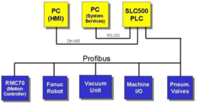 Figure 7: Die casting press control system block diagram
To perform the closed loop hydraulic control of the shot cylinder, the machine designers needed a motion controller that:
- Interfaces directly to PROFIBUS
- Supports position and pressure control of hydraulics, interfacing directly to proportional servo valves
- Is easy to program and tune
- Offers a good cost/performance tradeoff.
To fill these requirements, the designers selected motion controller that is optimized for systems requiring only one or two axes of precision motion control. The controller is supported by a software package that provides graphical tools to help designers develop control profiles and tune control loop parameters. The engineers used the software to do the initial design and tuning, and they will use it to further optimize the motion in the future.
By combining PROFIBUS communications and a precision hydraulic motion controller, the customer is confident that the new machine will produce castings that are more uniform and have a shorter process development cycle than those produced by previous die casting machines.
About the Author
Tim Gessner, European Director of Business Development at Delta Computer Systems, is responsible for sales and distribution management throughout Europe. Prior to this role, he worked for 17 years in engineering development and applications support for Delta, playing key roles in the development of RMC motion controllers. Gessner holds two Bachelor of Science degrees, two Master’s degrees, and a PhD from the University of Edinburgh in Scotland.
Delta Computer Systems, Inc.
For almost 40 years, Delta Computer Systems, Inc. has supplied motion controllers and other industrial products that enable better performing machines. Delta’s RMC Motion Controllers are used for hydraulic, pneumatic, and electric closed-loop control in a wide array of single- and multi-axis control and testing applications. For more information contact Delta at (360)254-8688, email technicalsales@deltamotion.com, or visit us at www.deltamotion.com.”